1 Principle Structure and Concept
Turbine flow meter utilizes the mean velocity of the fluid in the suspension fluid to sense the fluid's instantaneous flow and cumulative flow. It is generally composed of an impeller, a deflector, a permanent magnet, an induction coil, and a preamplifier. Turbine flow meter structure shown in Figure 1.
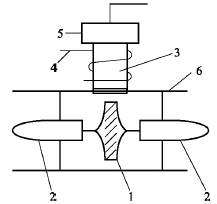
1—Impellers; 2—ducts; 3—permanent magnets; 4—induction coils;
5-preamplifier; 6-case.
Figure 1 Structure of turbine flowmeter
(1) Fluid viscosity. Because the internal friction will generate a magic wiper, the velocity of each layer is different. There is a pair of equivalent reversed forces at the contact surface of the adjacent layer, and the faster flow layer drives the slower layer. Accelerating the speed, the slower speed layer retards the faster layer and decelerates it. This blocking force is called internal friction force, and the fluid viscosity is a measure of internal friction and is the ability of the fluid to resist deformation. The viscosity of various fluids is different. For general fluids, viscosity is a function of temperature and pressure. The viscosity mentioned in the article is all kinematic viscosity, and the unit is cSt, 1 cSt=10-6 m2/s.
(2) Factor. The meter factor K refers to the number of pulses per unit volume of fluid flowing through the flowmeter. The unit is L-1. The formula is as follows:
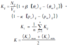
Where: Kij is the coefficient of the j-th inspection timing of the i-th verification point, L-1; Nij is the number of pulses measured by the flow meter display instrument at the j-th detection timing of the i-th verification point; Vij is the i-th verification point j The actual volume measured by the standard device at the time of the first inspection, L; β is the coefficient of body expansion of the fluid used for the verification in the verification state; (θs)ij, (θm)ij are the standard devices for the j-th inspection timing at the i-th verification point, respectively. And the liquid temperature at the flow rate, °C; κ is the compressibility coefficient of the liquid used in the verification; (ps)ij, (pm)ij are the j-test point and the j-th timing of the liquid pressure at the standard device and flow rate, respectively. ,Pa;n is the number of verifications per point; (Ki)max is the maximum value of Ki obtained by the flow meter at the flow verification point; (Ki) min is the minimum value of Ki obtained by the flow meter at the flow verification point.
(3) Linearity. Under the specified conditions, the percentage between the maximum deviation between the calibration curve of the turbine flow meter and the fitted straight line and the full-scale output is called linearity. The smaller the value, the better the linear characteristic. Calculated as follows:

Where: E is the linearity of the flow meter.
2 testing equipment and conditions
(1) Atmospheric pressure: 101,818 Pa.
(2) Media: Aviation lubricants.
(3) Verification device: Aviation lubricant flow standard device.
(4) Checked table: The model number is LWGY-15A, number 0906280, and the manufacturer is Shanghai Auto Meter 9 Instrument Co., Ltd.
3 Experimental data and analysis
According to the above test equipment and conditions, according to JJG1037-2008 "Turbine Flowmeter Verification Regulations", five points are tested at four different viscosities, and each point is verified 3 times. The obtained data is shown in Table 1 to Table 4; The frequency, flow rate, temperature, and coefficient in the table are each an average of 3 times for each point. The linearity of the instrument obtained from Table 1 is 8.9%, the meter coefficient is 528.61L-1; the linearity of the meter obtained from Table 2 is 6.3%, the meter coefficient is 553.89L-1; the linearity of the meter obtained from Table 3 is 2.6%, the meter The coefficient is 596.18L-1; the linearity of the instrument obtained from Table 4 is 2.2%, and the meter coefficient is 622.44L-1.
Table 1 Data with a viscosity of 93.24 cSt
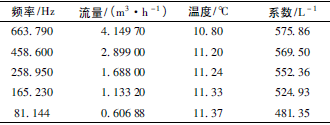
Table 2 Data at a viscosity of 52.14 cSt
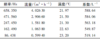
Table 3 Data at a viscosity of 16.28 cSt
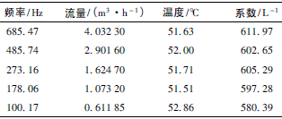
Table 4 Data with a viscosity of 7.16 cSt
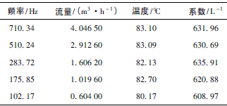
Due to the viscosity of the fluid, the lubricating oil creates a viscous drag moment when passing through the flow meter. From Table 1 to Table 4, it can be seen that when the lubricating oil viscosity changes from 93.24cSt → 52.14cSt → 16.28cSt → 7.16cSt, the coefficient of the turbine flowmeter (528.61L-1 → 553.89L-1 → 596.18L-1 → 622.44) L-1) and linearity (8.9%→6.3%→2.6%→2.2%) are gradually changing. When the flowmeter has a maximum viscosity of 93.24 cSt (datasheet 1), the linearity of the entire flowmeter is only 8.9%, and it cannot be used at all. In order to achieve the use requirement, only the measurement range is reduced. Through observation and calculation, it was found that when the flow rate was 2.8990 to 4.1497m3/h, the linearity was (575.86-569.50)/(575.86+569.50)×100%=0.56%, which met the JJG1037-2008 Turbine Flowmeter Verification Regulations. The maximum allowable error is 1.0%, which means that the meter is only qualified if it is used within these two points. When the viscosity is reduced to 7.16 cSt, the linearity range becomes wider. When the flow rate is 1.0196-4.0465m3/h, the linearity is (631.96-620.88)/(631.96+620.88)×100%=0.88%. The maximum allowable error.
In addition, it can be seen from Table 1 to Table 4 that the viscosity change of the flowmeter has a greater impact on the minimum flow point, and at four different viscosity, the coefficient has decreased significantly at the last point of the flow rate; and the viscosity is maximum. At 93.24 cSt, the coefficient changed from 524.93L-1 to 481.35L-1, the coefficient decreased by 43.58L-1; when the viscosity was 7.16cSt, the coefficient changed from 620.88L-1 to 608.97L-1, and the coefficient decreased only by 11.91. L-1. As can be seen from this, as the viscosity becomes smaller, the influence on the lower limit of the flow meter is also getting smaller and smaller. The effect of viscosity change on the characteristics of the turbine flowmeter is shown in Figure 2. The characteristic curve in Fig. 2 corresponds to Table 1, Table 2, Table 3 and Table 4 in order from bottom to top. The meter coefficient decreases with increasing viscosity. When used at higher viscosity, the meter coefficient and flow rate no longer remain linear. Relationships, therefore, turbine flowmeters that measure high viscosity must be corrected for viscosity and flow. The fitting formula for the characteristic curve in Figure 2 is:

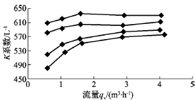
Figure 2 Effect of Viscosity Change on Turbine Flowmeter Characteristic Curve
For turbine flowmeters used to measure liquids, the meter factor K given by the manufacturer is usually calibrated with room temperature water, and the viscosity is only 1 cSt. In order to ensure the accuracy of the measurement, attention must be paid to the influence of the measured fluid viscosity on the characteristics of the flowmeter. Experiments show that when the liquid viscosity is greater than 15×10-6 m2/s, even if the same medium is used in the same medium, the measurement error will increase significantly. Therefore, it must be recalibrated under close working conditions to reduce the error.
Sms Spunmelt Nonwoven Production Line
The sms non-woven fabric production line is used to produce polypropylene fiber spun webs and hot-rolled reinforced non-woven fabrics. Using polypropylene as the main raw material, supplemented by color masterbatches and additives such as anti-oxidation, anti-pilling, and flame retardant, we can produce polypropylene spunbonded hot-rolled non-woven fabrics with different colors, different properties, and suitable for various purposes. It has different uses and is widely used in medical treatment, sanitation, agriculture, construction, geotechnical industry, making non-woven protective clothing, etc.
Various special treatments are carried out on non-woven fabrics to meet the requirements of customers for various special properties of non-woven fabrics. The treated non-woven fabric has anti-alcohol, anti-blood, and oil-resistant functions, and is mainly used in medical surgical gowns and surgical drapes. Antistatic treatment: Antistatic non-woven fabrics are mainly used as materials for protective equipment that have special environmental requirements for static electricity. Absorbent treatment: Absorbent non-woven fabrics are mainly used in the production of medical consumables, such as surgical drapes, surgical pads, etc. Flame-retardant treatment: Flame-retardant non-woven fabrics are widely used in furniture products and aviation products. Antibacterial deodorization and photocatalyst effect treatment: This kind of non-woven fabric is mainly used in the field of household products. Anti-ultraviolet treatment: Anti-ultraviolet, anti-aging non-woven fabrics are mainly used in agricultural covering fabrics, car covers and other fabrics where sun protection and anti-aging effects are required. Fragrance treatment: Fragrance non-woven fabrics are used in sanitary products (mint, lemon, lavender, etc.).
The composite production line can be replaced with different configurations to produce S, SS, SSS and other series of products to meet the needs of customers in the polypropylene spunbond non-woven market for different purposes.
Sms Spunmelt Nonwoven Production Line,Sms Non-Woven Fabric Making Machine,Sms Spunmelt Composite Non-Woven Fabric Machine,Sms Pp Spunbond Meltblown Making Machine,SMS spunmelt composite non-woven production equipment,SMS non-woven equipment
Changzhou Puyisen Machinery Technology Co., Ltd. , https://www.pysmachine.com
